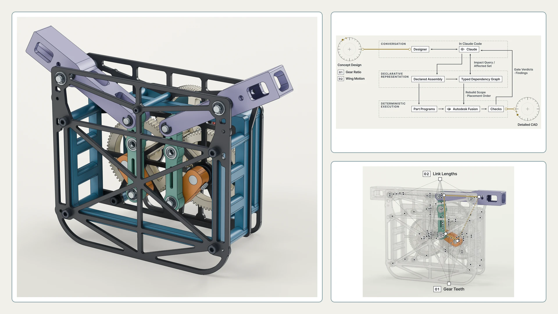
A large language model (LLM) coordinates concept calculations, parametric CAD generation and assembly verification for an ornithopter mechanism.
01 Concept to CAD
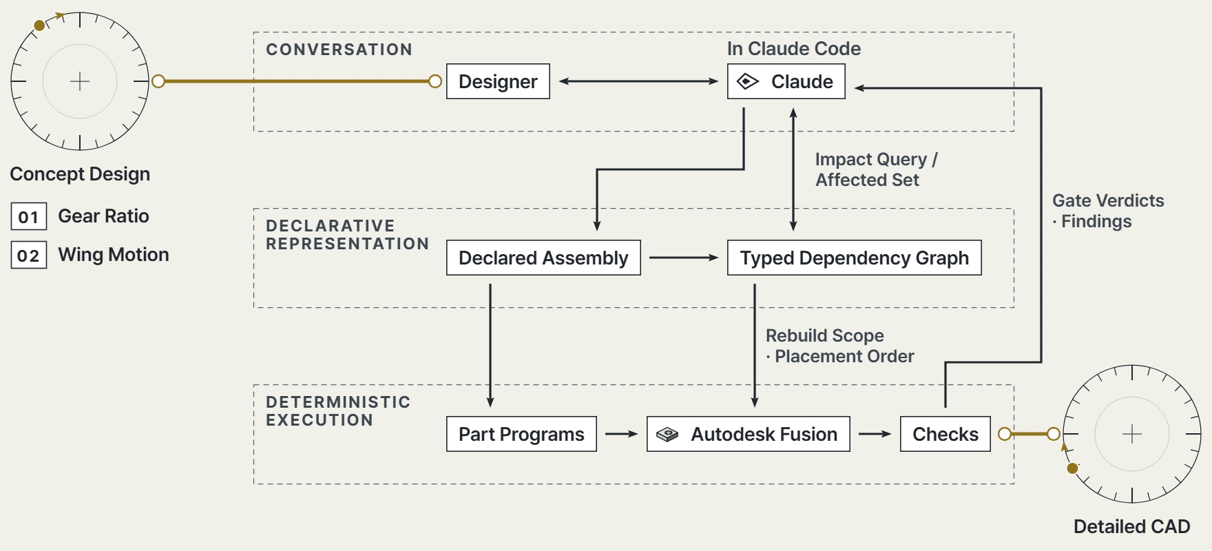
The concept-design workbench brings sizing, gear-train and linkage calculations into a shared design state. Numerical tools compute the design quantities, while the agent interprets the request and coordinates the required operations. Computed gear and linkage parameters then pass into the CAD catalogs used by the part programs.
02 Engineering Knowledge and Dependencies
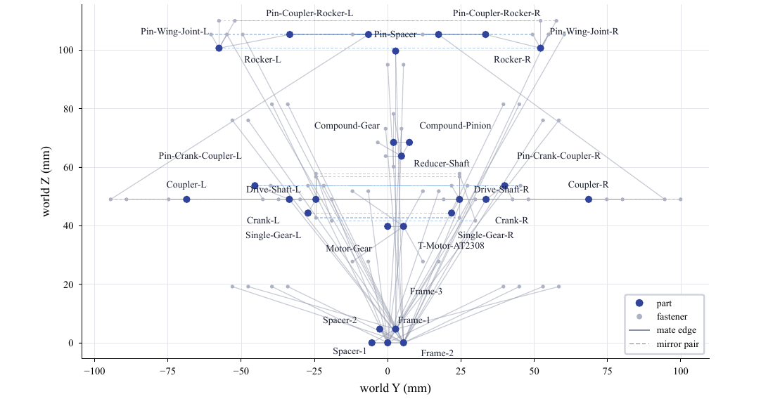
Shared catalogs define dimensions, and an assembly description records parts, mating interfaces and joints. These declarations produce a typed dependency graph, a network whose links distinguish assembly connections from parameter dependencies. The agent queries this graph to identify parts that need new geometry and parts that need new positions, together with the order in which to rebuild them.
03 Baseline Assembly
Agent-authored Python programs generate the parts with build123d. Their geometry and mating interfaces guide placement and joint creation in Fusion, a few parts per cycle. Each cycle checks interface alignment, joint health and interference, with multi-view inspection at review points. The agent uses the check results to correct a failed cycle before continuing. A crank-motion sweep checks interference at sampled positions of the assembled mechanism.
04 Design Changes
Two demonstrations start from the same baseline. The first changes the gear ratio and propagates the new dimensions and placements through the mechanism. The second passes wing-motion targets to a standalone numerical optimizer, then transfers the resulting linkage dimensions into CAD. Both carry the requested change through part regeneration, full reassembly and geometric verification.